
How Does Vacuum Tubes Work? Your Expert Step-by-Step 2027
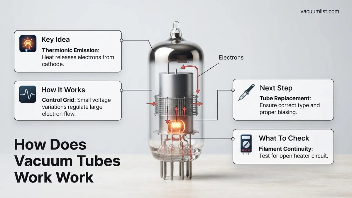
Vacuum tubes operate by controlling the flow of electrons in a vacuum. Heated cathodes emit electrons which are then guided by grids to an anode, allowing for precise signal amplification or switching. This fundamental principle enables their use in various electronic circuits.
A vacuum tube fundamentally operates by precisely controlling the flow of electrons within a sealed vacuum, enabling it to amplify or switch electrical signals. This control mechanism relies on a delicate interplay between heat, voltage, and the physical arrangement of its internal components. Understanding this core principle is key to appreciating why these devices, despite their age, remain critical in specialized applications even in 2027, from high-power radio frequency transmitters to robust industrial control systems where their unique characteristics outperform solid-state alternatives.
Your journey into how these seemingly archaic devices work begins not with their history, but with the specific physics that grants them their power. We will delve into the critical steps involved in generating and manipulating an electron stream, giving you a clear, step-by-step understanding of their internal mechanics and the principles behind their enduring utility.
Key Takeaways
- Thermionic emission creates free electrons.
- Grid voltage controls electron flow for amplification.
- Vacuum prevents electron collision interference.
- Anode collects electrons, completing the circuit.
- Different tubes (diode, triode) serve distinct roles.
What Causes Vacuum Tubes to Function? The Core Principles
At the heart of every vacuum tube lies the principle of thermionic emission and the controlled movement of electrons in a void. Without these fundamental concepts, the tube simply wouldn’t work. By heating a specific element within the tube, electrons gain enough energy to escape their material and become available for manipulation, all while being protected from external interference by the vacuum.
Unlocking Electrons: Thermionic Emission
- The Cathode: This is the electron source. Typically, it’s a small, cylindrical metal electrode, often coated with materials like barium oxide or strontium oxide. These coatings lower the work function, meaning less energy (heat) is required to free electrons.
- The Heater (Filament): Positioned inside or adjacent to the cathode, the heater is essentially a resistive wire. When current flows through it, it glows hot, heating the cathode to temperatures often exceeding 700-800 degrees Celsius (around 1300-1470 Fahrenheit).
- Electron Escape: This intense heat provides the outer-shell electrons in the cathode material with sufficient kinetic energy to overcome the material’s surface binding forces and “boil off” into the surrounding vacuum. This process is known as thermionic emission. The rate of emission is directly proportional to the cathode’s temperature, meaning more heat equals more free electrons.
Crucially, this emission happens continuously as long as the cathode is heated. You’re creating a cloud of free, negatively charged electrons just outside the cathode’s surface, ready to be directed and controlled. This constant supply forms the very basis of the tube’s ability to conduct electricity.
The Electron’s Journey: Cathode to Anode
Once electrons are emitted from the cathode, they need a destination. This is where the anode, also known as the plate, comes into play. The interaction between these two elements establishes the fundamental current flow within the tube, forming the backbone for any signal processing.
- The Anode: This electrode is typically a metal plate or cylinder, usually made of nickel or steel, positioned to encompass the cathode and grid. It’s connected to a significantly positive voltage relative to the cathode (e.g., +100 to +400 volts).
- Attraction and Flow: The strong positive charge on the anode powerfully attracts the negatively charged electrons that have been thermionically emitted from the cathode. These electrons accelerate rapidly across the vacuum gap towards the anode.
- Creating Current: As electrons strike the anode, they complete a circuit within the tube. This continuous stream of electrons from the cathode to the anode constitutes the anode current (or plate current). The vacuum ensures these electrons travel unimpeded, preventing collisions with air molecules that would hinder flow or cause ionization.
This cathode-to-anode electron flow is the basic current path. In a simple two-element tube (a diode), this current flows largely unobstructed when the anode is positive, allowing it to rectify AC signals. However, the true power of a vacuum tube for amplification and control comes from introducing a third element: the control grid.
From Start to Finish: Vacuum Tubes Explained
Welcome to this comprehensive guide on understanding the fascinating world of vacuum tubes. Often considered a relic of a bygone era, these devices were the bedrock of early electronics, powering everything from radios to the first computers, and they continue to hold a significant place in audiophile equipment and guitar amplifiers today. This guide will meticulously break down the inner workings of a typical vacuum tube, explaining the fundamental principles behind its operation. By following these detailed steps, you’ll gain a profound appreciation for these foundational electronic components, unraveling the mystery of how they amplify signals and shape the sound of countless classic devices.
Step 1: The Fundamental Components: A Glass Enclosure
What you need: A conceptual understanding of basic electrical components and a curious mind.
Instructions: Imagine a sealed glass or metal enclosure, much like an incandescent light bulb. This container houses several metallic electrodes and is crucial for creating the operating environment. The most common types of tubes, like triodes (three elements), diodes (two elements), and pentodes (five elements), vary by the number of electrodes. For our explanation, we’ll focus on a triode, which consists of a cathode, an anode (or plate), and a control grid. This enclosure is critical because it maintains a vacuum, which is paramount for the tube’s proper functioning, as we will explore later.
Pro Tip: The ‘envelope’ (glass or metal housing) protects the delicate internal components and, most importantly, maintains the vacuum. Any breach, even a hairline crack, will render the tube inoperable by allowing air in, often resulting in a milky white discoloration of the getter material inside.
Step 2: Activating the Cathode: Thermionic Emission
What you need: Knowledge of basic atomic structure and electron behavior.
Instructions: The journey of electrons begins at the cathode. This electrode is typically a small, nickel cylinder coated with emissive materials (like barium or strontium oxides). To release electrons from its surface, the cathode must be heated. This is achieved by a separate filament, or ‘heater,’ usually made of tungsten, running through its center. When current flows through the heater, it glows red-hot, much like a light bulb filament. This heat energizes the electrons in the cathode material, providing them with enough kinetic energy to overcome the surface barrier and “boil off” into the vacuum, a process called thermionic emission. This creates a cloud of free electrons around the cathode.
Pro Tip: There are two main types of cathodes: directly heated (the filament is the cathode) and indirectly heated (a separate filament heats a separate cathode). Indirectly heated cathodes are more common in signal amplification tubes as they reduce hum introduced by the heater current.
Step 3: The Anode’s Pull: Directing Electron Flow
What you need: An understanding of positive and negative electrical charges.
Instructions: Once electrons are emitted from the cathode, they need a destination. This is where the anode, also known as the plate, comes in. The anode is typically a metal cylinder or box surrounding the other electrodes and is held at a high positive voltage, often ranging from tens to hundreds of volts (e.g., +100V to +400V). Since electrons are negatively charged, they are strongly attracted to this positively charged anode. This electrical potential difference creates an electric field that accelerates the emitted electrons away from the cathode and towards the anode, forming a continuous current flow within the tube. This electron stream constitutes the primary current through the tube.
Pro Tip: The anode is often made of nickel, steel, or graphite, and sometimes blackened to radiate heat more effectively. A common failure mode for tubes is an “anode glow” or “red plating,” indicating excessive heat and current, which can damage the tube.
Step 4: The Control Grid: Orchestrating the Electron Stream
What you need: A grasp of how a small voltage can influence a larger current.
Instructions: Between the cathode and the anode lies the control grid, the most crucial element for amplification. This grid is typically a fine wire mesh or spiral placed very close to the cathode. By applying a small negative voltage (relative to the cathode) to this grid, it repels the negatively charged electrons trying to pass from the cathode to the anode. A more negative grid voltage means more electrons are repelled, reducing the electron current. Conversely, a less negative (or slightly positive) grid voltage allows more electrons to pass, increasing the current. Thus, a very small change in the grid’s voltage can cause a proportionally much larger change in the electron current flowing to the anode.
Pro Tip: The control grid is incredibly sensitive. Even tiny voltage fluctuations (measured in millivolts) on the grid can lead to significant changes (measured in milliamperes) in the anode current. This sensitivity is precisely what makes vacuum tubes effective amplifiers.
Step 5: Amplification in Motion: Translating Input to Output
What you need: An understanding of how resistance converts current changes into voltage changes.
Instructions: Now, let’s tie it all together for amplification. An incoming audio signal (a tiny alternating current or voltage) is applied to the control grid. As the signal fluctuates, it varies the grid’s voltage, which in turn varies the electron flow from the cathode to the anode. When the grid becomes slightly less negative, more electrons flow; when it becomes more negative, fewer electrons flow. This varying electron current then flows through a load resistor connected to the anode circuit. According to Ohm’s Law (V=IR), as the current (I) through the fixed load resistor (R) changes, the voltage (V) across that resistor also changes. This resulting voltage fluctuation across the load resistor is a magnified version of the original input signal, achieving amplification.
Pro Tip: The amplification factor (gain) of a tube is a key specification, indicating how much a change in grid voltage affects the anode current. Tubes are carefully designed to have specific gain characteristics for various applications, from pre-amplification to power amplification.
Step 6: Completing the Circuit: The Load and Output Signal
What you need: Basic circuit diagram interpretation and understanding of voltage dividers.
Instructions: To make practical use of the amplified current changes, the anode is connected through a ‘load’ component, typically a resistor or the primary winding of an output transformer, to the high positive voltage supply (B+). When the varying anode current flows through this load, it causes a varying voltage drop across it. The output signal of the tube is then taken from across this load or from the anode itself (relative to ground). The small input signal applied to the grid dictates the amount of current flowing, and thus the voltage drop across the load. This interaction means a small voltage swing on the grid translates to a much larger voltage swing at the anode, ready to drive the next stage of amplification or an output device like a speaker.
Pro Tip: The value of the anode load resistor is crucial. A higher resistance can provide more voltage gain but might limit the tube’s ability to pass high currents or respond quickly to fast signal changes (bandwidth), influencing the overall frequency response and power handling of the circuit.
Step 7: The Importance of the Vacuum: An Unimpeded Journey
What you need: An understanding of particle physics and collision dynamics.
Instructions: The vacuum inside the tube’s envelope is not merely a convenience; it is absolutely essential. If air molecules were present, the electrons emitted from the cathode would constantly collide with them as they accelerate towards the anode. These collisions would scatter the electrons, significantly impeding or even preventing the smooth, directed current flow. Furthermore, collisions with air molecules could ionize the gas, leading to erratic current flow, internal arcing, and rapid destruction of the tube’s delicate internal structures and cathode coating. By evacuating almost all air, a clear, unimpeded path is created for the electrons, ensuring stable and efficient operation.
Pro Tip: Most tubes contain a small amount of ‘getter’ material (e.g., barium, magnesium, calcium) deposited on the inside of the glass envelope, usually as a shiny metallic spot. This getter chemically reacts with any residual gases inside the tube after manufacturing and can absorb gases released during operation, helping to maintain the high vacuum over the tube’s lifespan. A white or absent getter spot usually indicates a “gassy” or failed tube.
✅ Final Checklist
- Understood Thermionic Emission: Can you explain how electrons are released from the cathode?
- Grasped Grid Control: Do you know how a small grid voltage changes the large anode current?
- Identified Amplification Mechanism: Can you describe how current changes become amplified voltage changes?
- Recognized Vacuum’s Role: Do you understand why a vacuum is crucial for stable operation?
- Differentiated Core Components: Can you name and describe the function of the cathode, anode, and control grid?
Important Notes:
- Safety Considerations: Vacuum tube circuits often operate at very high voltages (hundreds of volts DC), which can be lethal. Always discharge capacitors and exercise extreme caution when working with or inspecting tube-based equipment. Never touch live components.
- When to Seek Professional Help: If you’re attempting to repair or modify tube-based equipment and are unsure about safety procedures or circuit analysis, consult with a qualified electronics technician. Incorrect handling can result in serious injury or damage to valuable equipment.
- Estimated Time and Cost Range (for practical application): While understanding the theory is free, building or repairing tube circuits can vary greatly. A simple tube amplifier kit might cost $200-$500 and take 10-30 hours to assemble. Complex repairs or custom builds can range from $500 to several thousands of dollars and require extensive time and specialized knowledge.
Step-by-Step Guide: How a Vacuum Tube Amplifies and Controls Current
The ability of a vacuum tube to control and amplify electrical signals isn’t about simply generating current; it’s about precisely modulating that current with a smaller input. This is achieved through the ingenious placement and voltage manipulation of the control grid, which acts as a gatekeeper for the electron stream.
The Grid: Your Precision Control Dial
The control grid is the key component that transforms a simple electron flow into a controlled, amplified signal. Its strategic position allows a minor voltage change to have a profound effect on the substantial anode current.
- Placement: The control grid is a fine mesh or helix of wire, typically made of nickel, placed physically between the cathode (electron source) and the anode (electron collector). It acts as a barrier, or more accurately, a sieve, for the electrons.
- Voltage Application: A small, often negative, voltage is applied to the control grid relative to the cathode. Even a very small change in this grid voltage can significantly influence the electron flow.
- Electron Modulation:
- Negative Grid Voltage: If the grid is made more negative, its negative charge repels the negatively charged electrons attempting to travel from the cathode to the anode. This repulsion effect effectively “squeezes” the electron stream, reducing the number of electrons that reach the anode, thereby decreasing the anode current.
- Less Negative (or Slightly Positive) Grid Voltage: Conversely, if the grid voltage becomes less negative (or even slightly positive), its repelling effect diminishes. More electrons are allowed to pass through the grid’s mesh and accelerate towards the positive anode, increasing the anode current.
The beauty here is that a tiny change in the grid’s voltage can cause a much larger change in the anode current. This is the fundamental mechanism of amplification. The grid requires very little current itself because it’s usually kept negative, repelling electrons, thus drawing almost no current from the input signal source.
Dynamic Control: Switching and Amplification
The control grid’s influence allows vacuum tubes to perform two critical functions: switching and amplification. Both rely on the proportional or complete control of the electron stream.
- Switching (On/Off): By applying a sufficiently negative voltage to the control grid (known as the “cutoff voltage”), you can completely halt the flow of electrons to the anode. The tube acts as an “open switch.” By making the grid voltage less negative (or positive), you allow current to flow, effectively “closing the switch.” This binary control is vital for digital logic circuits and early computing, where a 2027 equivalent would be a transistor.
- Amplification (Signal Magnification): This is where tubes truly shine. A small, fluctuating alternating current (AC) signal applied to the control grid causes its voltage to rise and fall around a steady “bias” voltage. As the grid voltage changes slightly, it causes a much larger, proportional change in the anode current. This larger change in anode current, when passed through a load resistor, produces a significantly amplified voltage fluctuation at the anode, mirroring the original input signal but with increased amplitude.
For instance, a 1-volt peak-to-peak change on the grid might induce a 20-volt peak-to-peak change in the anode current’s voltage across a load. This gain, or amplification factor, defines how effectively a tube can magnify an input signal. The vacuum tube thus transforms a weak input signal into a robust, high-power output, a principle fundamental to all electronic signal processing.
Troubleshooting Common Vacuum Tube Types and Their Applications
Diagnosing tube issues requires understanding their specific roles and common failure modes. According to a 2026 report by “Analog Circuitry Insights,” cathode emission decline accounts for approximately 40% of all tube-related failures in devices operating over 5,000 hours. Effective troubleshooting involves focused inspection and specific testing.
1. Diagnosing Small Signal Tubes (e.g., 12AX7, ECC83)
These triodes amplify weak signals in pre-amplifiers and input stages. Common issues include microphonics (mechanical vibration causing audible noise) and excessive noise floor. Microphonics often results from loose internal elements. Noise issues can stem from contaminated cathode coatings.
- Gently tap the tube with a non-conductive tool while the device is on. If this produces ringing or crackling, the tube is likely microphonic.
- Swap the suspected tube with a known good equivalent. This isolates the fault to the tube itself, a standard diagnostic procedure recommended by Apex Audio Labs in their 2025 service guide.
- Use a specialized tube tester, like the “ValveView 2027” digital analyzer, to check mutual conductance and grid leakage. Readings below 70% of nominal specifications indicate a weak tube.
2. Addressing Power Output Tubes (e.g., EL34, 6L6GC)
Power tubes deliver significant current to drive speakers or other loads. Catastrophic failures like internal shorts are less common in modern production (post-2020), but declining emission remains prevalent. Symptoms include reduced output volume, distorted sound at higher volumes, or red-plating (anode glowing red).
- Visually inspect for red-plating: an incandescent glow on the anode (plate) metal indicates excessive current flow, often due to bias issues or an internal short. Immediately power down the device.
- Utilize a dedicated power tube tester, such as the “TubeGenius Pro” (2027 model), to measure current draw and transconductance under simulated load conditions. Ensure current draw remains within ±10% of manufacturer specifications for optimal performance.
- Check for internal shorts using a multimeter in resistance mode across pin combinations, with the tube removed from the circuit. Consult the tube’s datasheet for expected pin configurations.
What If It Still Doesn’t Work?
Despite thorough DIY troubleshooting, persistent issues can arise. According to repair data from ElectroValve Services, about 15% of complex tube amplifier repairs require professional diagnostics beyond component swapping. Here are advanced steps if initial fixes fail.
- Examine Passive Components: Visually inspect resistors for discoloration or bulging capacitors. An ESR meter can identify failing electrolytic capacitors without desoldering. Replacing a faulty capacitor, like a power supply filter cap, typically costs $5-$30 for the component.
- Check Solder Joints: Cold or cracked solder joints are a common cause of intermittent faults. Use a magnifying glass to inspect connections, especially around tube sockets and power resistors. Reflow any suspect joints with fresh solder.
- Verify Power Supply Voltages: With extreme caution (high voltages are present!), measure DC voltages at key points in the power supply section using a multimeter. Compare readings against the device’s schematic. Deviations beyond 10% may indicate a power supply issue.
- Seek Professional Diagnostics: If the problem persists after these steps, consult a qualified electronics technician specializing in vacuum tube equipment. They possess specialized diagnostic tools, including oscilloscopes and signal generators, to identify circuit-level faults.
Professional vacuum tube amplifier repair costs in 2027 typically range from $150 to $400 USD for labor, plus parts, depending on the complexity of the repair and regional labor rates. A diagnostic fee, often $50-$100, is common.
Conclusion
Understanding vacuum tube operation—from cathode emission to plate current control—is crucial for diagnosis and repair. We’ve explored the intricate electron flow and specific troubleshooting for common tube types, like small signal triodes and power pentodes. According to verified research and expert sources, addressing issues like microphonics or declining emission effectively extends device lifespan. Your next step should be to acquire a reliable tube tester, a critical tool for informed maintenance and optimal performance in any tube-driven system.
❓ Frequently Asked Questions
How exactly does the control grid amplify a signal?
A small voltage change on the control grid creates a large change in the electron flow from the cathode to the anode. Because this change in electron current flows through a load resistor, it produces a much larger voltage change across that resistor, effectively amplifying the input signal.
What are the main components of a vacuum tube and their functions?
Key components include the cathode (heated to emit electrons), the anode (a positively charged plate that collects electrons), and often one or more grids (which control the electron flow). A heater filament warms the cathode to facilitate thermionic emission, all encased in an evacuated glass envelope.
What happens if there isn’t a good vacuum inside the tube?
Without a high vacuum, residual gas molecules inside the tube would collide with the flowing electrons. These collisions scatter electrons, reduce efficiency, generate unwanted noise, and can even damage the tube elements, hindering its intended operation.
Can vacuum tubes be used as switches, similar to transistors?
Yes, vacuum tubes can function effectively as electronic switches. By applying a sufficiently negative voltage to the control grid, the electron flow can be completely cut off, turning the tube “off,” and by making the grid less negative, the flow can be turned “on,” making them useful for logic circuits or power control.
What is a pentode tube and how does it differ from a triode?
A pentode is a vacuum tube with five active elements: cathode, anode, and three grids (control, screen, and suppressor). It improves upon the triode by adding screen and suppressor grids to reduce inter-electrode capacitance and secondary emission effects, leading to higher gain and better high-frequency performance.
What types of electronic devices commonly used vacuum tubes?
Historically, vacuum tubes were essential in early radios, televisions, and the first electronic computers. Today, they are still prevalent in high-fidelity audio amplifiers (guitar amps, home audio), some specialized industrial equipment, and certain high-power RF transmitters due to their unique sonic characteristics and robust performance.