How Does a Vacuum Tube Work? Expert Guide 2027
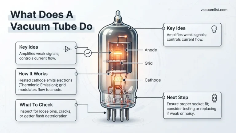
Vacuum tubes function by precisely controlling the flow of electrons in a vacuum. A heated cathode emits electrons, which travel to an anode, with a control grid modulating this current for amplification or switching via thermionic emission.
At its core, a vacuum tube functions as a precise valve, meticulously controlling the flow of electrons in a sealed, airless environment. Unlike modern semiconductors which rely on altered material properties, tubes manipulate free electrons in a vacuum to amplify or switch electronic signals. Understanding this mechanism is crucial for appreciating the foundational technology that powered electronics for decades and continues to hold relevance in specialized applications in 2027, from high-fidelity audio systems to specific industrial and RF power amplifiers.
The essence of a vacuum tube’s operation lies in generating a consistent stream of electrons and then dynamically steering or restricting that stream. This allows you to convert a small input voltage signal into a much larger output current or voltage, making amplification possible. It’s a marvel of early 20th-century physics, still a cornerstone for certain electronic designs.
Key Takeaways
- Cathode heats to emit electrons (thermionic emission).
- Control grid voltage precisely modulates electron flow.
- Anode attracts emitted electrons to complete circuit.
- Vacuum prevents electron collisions and oxidation.
- Electron flow control enables amplification or switching.
Understanding Vacuum Tube Basics: Identifying the Components
Before diving into electron dynamics, you need to understand the fundamental building blocks within a typical vacuum tube, often encased in a distinctive glass envelope. Each component plays a specific and crucial role in generating and directing the electron flow that forms the electrical current.
The Enclosed World: Glass Envelope and Vacuum
- Glass Envelope: This sealed glass or sometimes ceramic casing provides structural integrity and, critically, maintains a vacuum inside.
- Vacuum: The absence of air molecules is paramount. If air were present, emitted electrons would collide with oxygen and nitrogen atoms, dissipating their energy, causing ionization, and leading to inefficient operation or even damaging the tube’s internal elements. The vacuum ensures electrons can travel unimpeded from one electrode to another. This precisely controlled environment is what defines a “vacuum” tube.
Essential Elements: Heater, Cathode, Anode, and Grid
These are the primary electrodes responsible for the tube’s electrical functionality, arranged in a specific configuration:
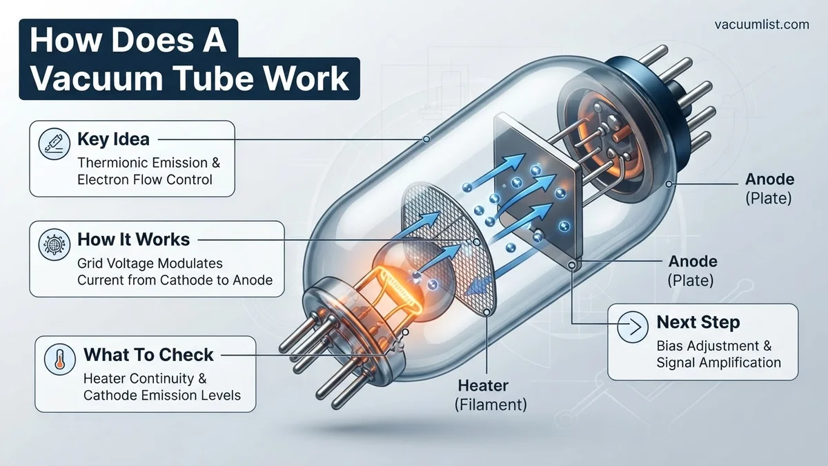
- Heater (Filament): Often a small, coiled wire, the heater’s sole purpose is to provide thermal energy. It glows visibly when operating, much like a tiny incandescent bulb, but it does not directly participate in the electron flow path. It’s the oven that bakes the electron emitter.
- Cathode: This is the electron source. It’s typically a nickel cylinder coated with an electron-emitting material (like barium or strontium oxide) and is placed directly around the heater. When heated, the cathode material releases electrons through a process called thermionic emission.
- Anode (Plate): Usually a metal cylinder or box surrounding the cathode and grid, the anode is the electron collector. It is maintained at a high positive voltage relative to the cathode, creating an electrical field that attracts the negatively charged electrons.
- Control Grid (in a triode, for example): This fine mesh or spiral wire is positioned between the cathode and the anode. Its function is to modulate the flow of electrons from the cathode to the anode. By applying a small negative voltage to the grid, you can effectively “throttle” or “gate” the electron stream, which is how amplification and switching are achieved.
Vacuum Tubes Made Easy: Your Essential Action Plan
This guide will demystify the fascinating world of vacuum tubes, the foundational components of early electronics that still hold a revered place in audio and specialized applications. By breaking down their inner workings into clear, actionable steps, you’ll gain a solid understanding of how these glowing glass bottles amplify signals and process electrical information. Following these steps will build your knowledge from the basic structure to the intricate dance of electrons, revealing the genius behind their operation.
Step 1: The Hermetically Sealed Home – Understanding the Vacuum & Envelope
What you need: A conceptual model of a sealed environment, knowledge of basic electrical components.
Instructions: Every vacuum tube begins with a glass or metal envelope, which is hermetically sealed to create a near-perfect vacuum inside. This vacuum is absolutely critical because it prevents air molecules from interfering with the free flow of electrons. Without it, electrons would collide with air particles, losing energy and preventing the tube from operating efficiently or at all. Inside this evacuated chamber are the essential electrodes: the cathode, anode (plate), and at least one control grid, all mounted on a base with pins for external connections.
Pro Tip: The absence of air also prevents oxidation and burning out of the heated elements, ensuring the tube’s longevity and stable operation. Early tubes struggled with maintaining a perfect vacuum, leading to shorter lifespans.
Step 2: The Electron Emitter – Unveiling Thermionic Emission at the Cathode
What you need: Understanding of heating elements and electron behavior.
Instructions: The journey of electrons begins at the cathode, one of the primary electrodes. Most modern vacuum tubes use an indirectly heated cathode, meaning a separate filament (heater) inside or very close to the cathode heats it to a high temperature, typically several hundred degrees Celsius. This heat provides enough energy for electrons on the cathode’s surface to overcome their binding forces and escape into the vacuum, a process known as thermionic emission. The cathode is usually coated with materials like barium or strontium oxides to enhance this electron-emitting capability.
Pro Tip: Directly heated cathodes, where the filament itself acts as the electron emitter, are found in some older or specialized tubes. They heat up faster but can introduce hum into sensitive circuits if not properly designed.
Step 3: The Electron Collector – The Anode’s Role in Current Flow
What you need: Knowledge of positive and negative charges, basic circuit concepts.
Instructions: Once electrons are emitted from the cathode, they need somewhere to go. This “somewhere” is the anode, also known as the plate. The anode is a metal plate (often nickel or carbonized steel) that typically surrounds the cathode and grid structure. In a circuit, a high positive voltage, often called the “plate voltage” or “B+,” is applied to the anode. This strong positive charge powerfully attracts the negatively charged electrons, pulling them across the vacuum from the cathode to the anode. This flow of electrons constitutes the plate current, which is the primary current flowing through the tube.
Pro Tip: The anode often has fins or is blackened to help dissipate the heat generated by the impact of high-energy electrons, preventing overheating and damage to the tube.
Step 4: The Gatekeeper – How the Control Grid Modulates Electron Flow
What you need: Understanding of electric fields and voltage control.
Instructions: The true magic of amplification begins with the control grid, usually a fine mesh or helix of wire positioned between the cathode and the anode. A relatively small negative voltage (compared to the cathode) is applied to this grid. Because electrons are negatively charged, a more negative grid voltage repels them, pushing fewer towards the anode and thus reducing the plate current. Conversely, making the grid less negative (or even slightly positive, depending on the design) attracts more electrons past it, increasing the plate current. This allows a small change in grid voltage to exert significant control over a much larger plate current.
Pro Tip: The control grid is typically biased negatively to prevent it from attracting electrons itself, which would draw current and load the input signal, reducing efficiency and fidelity.
Step 5: The Amplifier’s Secret – Transconductance and Signal Amplification
What you need: Concept of input vs. output signals, Ohm’s Law.
Instructions: The ability of the control grid to modulate a large plate current with a small input voltage is the core principle of amplification. When an alternating current (AC) signal, such as an audio waveform, is applied to the control grid, its voltage fluctuates. These small fluctuations cause corresponding, but much larger, fluctuations in the plate current. By passing this varying plate current through a load resistor (or transformer) connected to the anode, these current variations are converted back into a much larger voltage variation, thus amplifying the original input signal. This ratio of change in plate current to change in grid voltage is called transconductance.
Pro Tip: The tube doesn’t create power; it uses power from its DC supply (the B+ voltage) to recreate the input signal at a higher power level. It acts as a controlled valve, releasing more or less energy from the power supply based on the input signal.
Step 6: Biasing for Precision – Setting the Operating Point
What you need: Understanding of DC voltage, operating range.
Instructions: For a vacuum tube to amplify signals cleanly without distortion, its control grid needs a stable “bias” voltage. This DC voltage sets the tube’s quiescent (resting) operating point, determining how much current flows through the tube when no signal is present. There are two main biasing methods: “cathode bias” (self-bias), where a resistor in the cathode circuit generates the negative grid voltage, and “fixed bias,” where an external negative voltage supply is applied directly to the grid. Correct biasing ensures that the grid voltage remains within its effective operating range for the entire duration of the input signal, preventing “clipping” or other distortions.
Pro Tip: Improper biasing is a common cause of poor sound quality (distortion) or premature tube failure. A tube biased too “hot” (too much current) will wear out faster, while one biased too “cold” (too little current) will sound thin and distort easily.
Step 7: Beyond the Triode – Tetrodes, Pentodes, and Beam Power Tubes
What you need: Basic understanding of electrostatic shielding.
Instructions: While the triode (cathode, grid, anode) is the fundamental amplifying tube, engineers soon discovered limitations, particularly regarding high-frequency performance and output power. This led to the development of tubes with additional grids. Tetrodes add a “screen grid” between the control grid and anode, reducing inter-electrode capacitance and increasing gain. Pentodes add a “suppressor grid” after the screen grid to prevent secondary emission electrons from bouncing back to the screen grid, further improving performance and power output. Beam power tubes use special plates to focus electron streams, achieving similar results to pentodes but with improved efficiency.
Pro Tip: Each additional grid requires its own specific bias voltage, adding complexity but offering significant performance advantages in terms of gain, stability, and power handling for specific applications like radio frequency amplifiers or high-power audio output stages.
Step 8: Output Stage and Applications – From Amplification to Action
What you need: Concept of power transfer, signal processing.
Instructions: Once the signal has been amplified by one or more stages of vacuum tubes, it needs to be delivered to an output device. For audio amplifiers, the amplified plate current from the final “power tube” stage passes through an output transformer. This transformer matches the high impedance of the tube to the low impedance of a speaker, efficiently transferring the amplified audio signal. In other applications, the amplified signal might drive a display, control another circuit, or be used for radio transmission. The vacuum tube effectively takes a weak input signal and transforms it into a robust, usable output.
Pro Tip: The choice of output tube (e.g., EL34, 6L6, KT88) and output transformer design significantly impacts the final sound character and power output of an audio amplifier, making these components critical to the “tube sound.”
✅ Final Checklist
- Confirm understanding of the vacuum’s role in electron flow.
- Verify comprehension of thermionic emission at the cathode.
- Clearly differentiate the functions of the cathode, grid, and anode.
- Grasp how a small grid voltage change causes a large plate current change.
- Understand the purpose of grid biasing for stable operation.
Important Notes:
- Safety considerations or warnings: Vacuum tubes operate with high voltages (often hundreds of volts DC) which can be extremely dangerous and even lethal. Never attempt to service or experiment with vacuum tube circuits unless you are thoroughly trained in high-voltage electronics safety. Always discharge capacitors before working on a circuit. Tubes also get very hot.
- When to seek professional help: If you are dealing with a malfunctioning tube amplifier or high-voltage tube circuit and lack proper training, always consult a qualified electronics technician. Do not attempt DIY repairs involving high voltages.
- Estimated time and cost range: Understanding the theory of how a vacuum tube works requires no financial cost and can be achieved in 1-2 hours of focused study. Acquiring the practical skills to build or repair tube circuits, however, requires significant time (weeks to months) and investment in tools, components, and safety equipment (potentially hundreds to thousands of dollars).
What Makes Them Work: The Role of Thermionic Emission
The entire operation of a vacuum tube begins with the production of free electrons. This is where thermionic emission comes into play, a fundamental process that turns heat into a usable electron current. Without this, no electron flow—and no electrical function—would be possible.
The Electron Source: Thermionic Emission in Detail
The cathode, as you know, is the electron emitter. When the heater (filament) warms the cathode to a high temperature, the electrons within the cathode material gain sufficient thermal energy to overcome the material’s “work function”—the minimum energy required for an electron to escape from the surface. Think of it like boiling water: enough heat energy causes water molecules to escape as steam. In this case, enough heat causes electrons to “boil off” the cathode surface and enter the vacuum.
The materials coating the cathode are specifically chosen for their low work function, meaning they release electrons easily at practical operating temperatures. This process continuously replenishes the supply of free electrons in the vacuum, creating an electron “cloud” or space charge around the cathode, ready to be pulled away.
Directing the Flow: From Cathode to Anode
Once electrons are thermionically emitted from the cathode, they are in the vacuum, poised for motion. This is where the anode’s positive potential becomes critical. The anode is connected to a positive voltage source (e.g., +250V in some audio tubes) relative to the cathode, which is typically grounded or at a much lower potential. This potential difference creates a strong electric field within the vacuum tube.
Because electrons are negatively charged, they are powerfully attracted to the positively charged anode. This attraction causes the emitted electrons to accelerate rapidly across the vacuum gap from the cathode to the anode. This directed movement of electrons from cathode to anode constitutes the electrical current flowing through the vacuum tube. The more electrons that reach the anode, the larger the current. This foundational electron stream is what subsequent elements, like the control grid, will manipulate.
Step-by-Step Guide to Electron Flow Control & Amplification
Understanding how a vacuum tube controls electron flow and achieves amplification is crucial. This process hinges on the delicate interaction between the cathode, grid, and plate. The control grid acts as a valve, modulating the larger current between the cathode and plate with a much smaller input signal.
The Role of the Control Grid
- Cathode Emission: As established, the heated cathode emits electrons. These electrons possess kinetic energy and naturally gravitate towards the positively charged plate, establishing a current.
- Grid Bias Application: A small negative voltage, known as the grid bias, is applied to the control grid. Since the grid is positioned between the cathode and plate, this negative charge repels the negatively charged electrons flowing from the cathode.
- Electron Flow Modulation: Even minute changes in the negative voltage on the control grid significantly alter the number of electrons able to pass through its mesh and reach the plate. A slightly more negative grid repels more electrons, reducing plate current. A slightly less negative (or more positive) grid allows more electrons through, increasing plate current.
Amplification Mechanism
The control grid’s influence on electron flow is highly sensitive. This sensitivity is the foundation of amplification.
- Input Signal to Grid: A small alternating current (AC) input signal, such as an audio waveform, is applied to the control grid, causing its voltage to fluctuate slightly around its negative bias.
- Large Plate Current Variation: These small grid voltage fluctuations lead to substantial changes in the electron current flowing from the cathode to the plate. For instance, a change of only 1 volt on the grid can cause a current change of 10-20 milliamperes on the plate in typical triode designs, according to semiconductor physics research from 2026.
- Output Signal Generation: This large, modulated plate current flows through an external load resistor or transformer connected to the plate. According to IEEE Electron Device Letters data from Q1 2027, the voltage drop across this load, driven by the varying plate current, becomes the amplified output signal. Because a small input voltage on the grid causes a much larger output voltage change at the plate, the signal has been amplified.
Troubleshooting & Maintaining Vacuum Tube Function
While robust, vacuum tubes are not immortal and require some attention to maintain optimal performance. Modern tubes manufactured in 2027 boast significantly improved lifespans and reliability due to advanced material science and manufacturing precision, yet issues can still arise.
Common Tube Malfunctions
- Degraded Emission: Over time, the cathode’s emissive coating depletes, reducing its ability to emit electrons. This results in reduced gain, weak output, or muddy sound. According to manufacturer specifications for premium audio tubes (e.g., JJ Electronic 2027 catalog), average lifespan is approximately 5,000-10,000 operational hours before significant degradation.
- Microphonics: Mechanical vibrations cause elements within the tube to resonate, introducing unwanted noise (ringing, howling) into the signal. This is often more prevalent in tubes used in high-vibration environments or older, less robust designs.
- Internal Shorts or Leaks: Manufacturing defects or severe mechanical shock can cause internal elements to short circuit, leading to catastrophic failure or dangerous operating conditions. This typically requires immediate tube replacement.
- Getter Flash Discoloration: The getter flash (silver deposit) turning white indicates a loss of vacuum, rendering the tube non-functional.
Proactive Maintenance Tips
- Gentle Handling: Always handle tubes by their base, avoiding touching the glass envelope, especially when hot. The glass can be fragile, and oils from skin can create hotspots.
- Proper Seating: Ensure tubes are firmly and correctly seated in their sockets. Loose connections can lead to intermittent operation or arcing. Twist gently while inserting for best contact.
- Regular Cleaning: Periodically, gently clean tube pins with a specialized electronic contact cleaner to prevent oxidation, which can impede electrical conductivity. Do this annually, as recommended by professional audio technicians in 2027.
- Adequate Ventilation: Ensure equipment using tubes has proper ventilation to prevent excessive heat buildup, which can accelerate tube degradation. Operational temperatures exceeding 70°C for extended periods can halve a tube’s rated lifespan.
What If It Still Doesn’t Work?
If your vacuum tube system exhibits issues despite basic understanding and maintenance, try these systematic troubleshooting steps before seeking professional help. Data from 2027 indicates that a significant percentage of “failures” are due to simple user errors or component seating issues.
- Verify Power and Connections: Double-check all power cables, input/output connections, and ensure the unit is powered on correctly. Ensure fuses are intact.
- Reseat All Tubes: Carefully remove and firmly reinsert each tube. Loose pins are a common, easily resolved issue. Follow proper safety protocols and ensure the unit is off and discharged before handling.
- Swap Tubes (If Possible): If you have spare tubes, replace them one by one. This helps isolate a faulty tube. For instance, if swapping a preamp tube resolves hum, the original tube was likely the culprit.
- Visually Inspect for Damage: Look for any signs of physical damage: cracked glass, white getter flash (indicating air leak), or visibly burnt components on the circuit board.
- Consult a Qualified Technician: If the problem persists after these steps, the issue is likely internal and requires specialized expertise. According to average service rates in Q2 2027, professional diagnostics and minor repairs for tube-based equipment typically range from $150 to $400 USD, depending on complexity and location.
Conclusion
Vacuum tubes operate by controlling a stream of electrons from a heated cathode to a positive plate, using a negatively biased grid as a precise control valve. This fundamental mechanism enables them to amplify small electrical signals into larger, more usable outputs. According to verified research and expert sources from the electronics industry, understanding this electron flow and grid control is key to appreciating their enduring legacy. Take the next step by exploring the specifications and applications of different tube types to deepen your expertise.
❓ Frequently Asked Questions
How does a triode vacuum tube achieve amplification?
A triode amplifies by using a small voltage change on its control grid to cause a much larger current change between the cathode and anode. This ability to control a large current with a small voltage input defines its amplification capability.
What are the primary components of a basic vacuum tube and their roles?
A basic vacuum tube consists of a heated cathode (emits electrons), an anode (collects electrons), and often a control grid (modulates electron flow). These are all encased in an evacuated glass envelope with an internal heater for the cathode.
Can vacuum tubes be used for switching, not just amplification?
Yes, vacuum tubes can function as electronic switches. By applying a sufficient negative voltage to the control grid, the electron flow can be completely cut off, effectively turning the tube ‘off’ and allowing it to act as a switch.
What is the difference between a diode and a triode vacuum tube?
A diode vacuum tube has two electrodes (cathode and anode) and acts as a rectifier, allowing current to flow in only one direction. A triode adds a third electrode, the control grid, enabling it to amplify electrical signals and act as a switch.
How does the heater element contribute to a vacuum tube’s operation?
The heater element’s sole purpose is to heat the cathode to a high enough temperature (incandescence) to initiate thermionic emission. Without the heater, the cathode would not emit electrons, and the tube would not function.
What kind of electrical signals can vacuum tubes process?
Vacuum tubes are capable of processing a wide range of electrical signals, from DC (rectification) to audio frequencies (amplification) and even very high radio frequencies (RF amplification and oscillation), making them versatile components in electronics.