
How Do Vacuum Tubes Work Expert Guide for 2026
At their core, vacuum tubes work by heating a cathode to boil off electrons, which are then controlled by a grid and collected by an anode to amplify electrical signals. This fundamental process of thermionic emission forms the backbone of vintage audio gear, guitar amplifiers, and high-end electronics. Understanding this electronic flow reveals why these components continue to deliver unique warmth and performance.
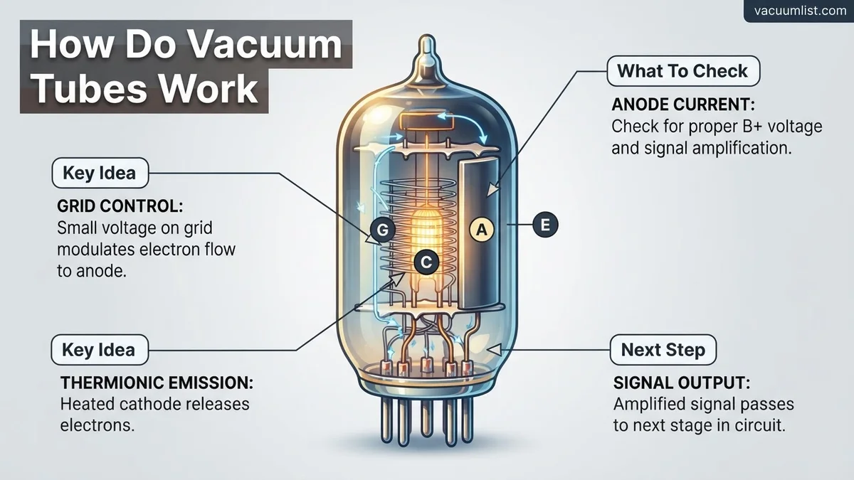
Vacuum tubes control electrical signals by boiling electrons off a heated metal cathode and guiding them through a high-vacuum glass envelope toward a positively charged anode. This fundamental process of thermionic emission allows a tiny voltage on a control grid to modulate a massive stream of moving electrons, achieving signal amplification and rectification without solid-state semiconductors.
Even in 2026, audiophiles and high-end guitar amplifier designers rely on vacuum tubes for their unique harmonic distortion and overload characteristics. Understanding how these glass envelopes function physically helps you troubleshoot vintage gear, maintain boutique audio systems, and appreciate the raw analog engineering behind thermionic devices.
Key Takeaways
- Cathodes release electrons when heated through a process called thermionic emission.
- The control grid acts like an electronic gate, regulating the flow of electrons.
- The anode collects the flowing electrons to complete the electrical circuit.
- Triodes combine these three elements to achieve signal amplification and rectification.
- Modern applications rely on tubes for warm saturation in guitar amps and audiophile gear.
What Causes Electron Flow: The Physics Behind Vacuum Tubes
Thermionic Emission and the Cathode
The entire operation of a vacuum tube starts with heat. Inside the glass envelope, a filament heats up a coated metal cylinder known as the cathode. As the cathode reaches temperatures often exceeding 700 degrees Celsius, electrons gain enough thermal kinetic energy to break free from the metal’s surface barrier.
- The Filament: Acts as a miniature heater, either directly warming the cathode or sitting inside an insulated ceramic sleeve.
- The Electron Cloud: Freed electrons form a dense spatial charge cloud directly surrounding the glowing cathode surface.
- The Vacuum: Removing all air molecules prevents electrons from colliding with gas atoms, ensuring they travel in a straight line toward their destination.
The Control Grid and Anode Plate
Once electrons hover around the cathode, they need direction. The anode (or plate) sits at the outermost perimeter of the internal structure, holding a high positive voltage that forcefully attracts the negatively charged electrons across the vacuum.
- The Control Grid: Positioned directly between the cathode and anode, this fine wire mesh acts like a traffic gate.
- Voltage Modulation: Applying a small negative voltage to the grid repels passing electrons, reducing the overall current flowing to the plate.
- Amplification: A minuscule voltage fluctuation on the grid creates massive, proportional swings in the high-voltage current rushing from cathode to anode.
Master Vacuum Tubes in 7 Simple Steps
Before the invention of the microscopic silicon transistor, the world of electronics was powered by the warm, glowing magic of vacuum tubes (or thermionic valves). Whether you are restoring a vintage guitar amplifier, repairing a classic radio, or simply curious about vintage audio fidelity, understanding the physics behind these glass cylinders is essential. This guide walks you through the fundamental mechanics of how vacuum tubes manipulate electrical currents to amplify sound and process signals, breaking down complex physics into clear, manageable concepts.
Step 1: Creating the Absolute Vacuum
What you need: A glass or ceramic envelope, high-powered evacuation vacuum pumps, and a hermetic sealing mechanism.
Instructions: The journey of a vacuum tube begins inside an evacuated glass chamber from which all air and gases have been forcefully extracted. If air were left inside the tube, the internal metal components would instantly oxidize and burn out at high operating temperatures. Manufacturers use industrial vacuum pumps to suck out nearly all atmospheric molecules, leaving a near-total vacuum. This empty space ensures that electrons can travel freely from one side of the tube to the other without colliding with stray gas molecules that would otherwise scatter or disrupt their targeted trajectory.
Pro Tip: Look closely at the top of an old tube; the silvery, metallic patch you often see is called the getter. It reacts with any residual gases left after sealing to maintain a pure vacuum over the lifespan of the tube.
Step 2: Heating the Cathode (Thermionic Emission)
What you need: A heater filament, a cathode sleeve coated with barium and strontium oxides, and a low-voltage power source (typically 6.3V or 12.6V).
Instructions: To make a vacuum tube work, you must first generate a supply of free electrons. This is achieved through a process called thermionic emission. Inside the tube sits a heater filament, much like the tiny wire inside an incandescent light bulb. When electricity flows through this heater, it glows red-hot, transferring thermal energy to the surrounding cathode sleeve. This sleeve is coated with specialized metal oxides that have a low work function, meaning they release electrons easily when heated. As the cathode gets blazing hot, it begins to boil off a cloud of negatively charged electrons into the surrounding vacuum space.
Pro Tip: Never power on a tube amplifier without the speakers or load connected, as the unmitigated thermal and electrical stress can damage both the cathode and the output transformer.
Step 3: Accelerating Electrons via the Anode (Plate)
What you need: A high-voltage DC power supply (ranging from 150V to 500V+) and a metal plate (anode) usually made of nickel or steel.
Instructions: Once the cathode is actively boiling off electrons, they need a destination. Positioned opposite the cathode is the anode, commonly referred to as the “plate.” You must apply a strong positive direct current (DC) voltage to this plate. Because opposite charges attract, the intensely positive plate acts like a powerful magnet for the negatively charged electron cloud hovering around the hot cathode. The electrons accelerate rapidly across the physical vacuum gap, slamming into the plate and creating a continuous flow of electrical current through the tube circuit. This movement of electrons is the fundamental current that carries your audio or radio signal.
Pro Tip: Plates can get extremely hot during operation. If a tube’s plate begins to glow bright cherry-red or orange, it indicates excessive current draw, meaning you need to shut down the circuit immediately to prevent a catastrophic blowout.
Step 4: Controlling the Current with the Control Grid
What you need: A fine wire mesh or spiral coil (the control grid) positioned directly between the cathode and the anode.
Instructions: A diode (a two-element tube) can only allow current to flow in one direction, which is useful for power rectification. However, to amplify a weak signal, you need a triode, which introduces a third element: the control grid. This grid is a physical barrier made of tightly wound wire placed right in the path of the traveling electrons. By applying a negative voltage to this grid, you create an electrostatic repulsive force. Even tiny changes in the grid’s negative voltage will dramatically alter how many electrons make it past the grid to the plate. This ingenious valve-like mechanism allows a tiny input voltage change to control a massive stream of electrons.
Pro Tip: Think of the control grid as a venetian blind: a small flick of your wrist (a tiny voltage change) can block or allow a massive beam of sunlight (the electron current) to flood through the room.
Step 5: Adding Auxiliary Grids for Advanced Amplification
What you need: Additional wire meshes known as the screen grid and suppressor grid (found in tetrodes and pentodes).
Instructions: While triodes are fantastic, they suffer from a limitation called interelectrode capacitance, which can cause unwanted high-frequency oscillations or feedback. To solve this, engineers added more grids. The screen grid (placed between the control grid and plate) is held at a fixed positive voltage, shielding the control grid and drastically increasing the tube’s gain. In a pentode, a fifth element called the suppressor grid is added to catch stray “secondary emission” electrons that bounce backward off the plate. These multi-grid configurations allow modern tube amplifiers to achieve ultra-high efficiency, massive gain, and pristine frequency response across complex musical passages.
Pro Tip: When replacing power tubes in a guitar amplifier, make sure you match the tube type (e.g., swapping a 6L6 for another 6L6 rather than an EL34) unless the amp is specifically designed with a multi-bias switch.
Step 6: Delivering the Output Signal to Your Circuit
What you need: An output transformer, decoupling capacitors, and a load (such as a speaker cone or headphones).
Instructions: The ultimate goal of this entire electron dance is to produce a usable, highly amplified output signal. As the current flowing to the plate fluctuates in exact harmony with the tiny audio signal applied to the control grid, it creates a fluctuating AC voltage riding on top of the high DC plate voltage. This combined signal is then routed through an output transformer. The transformer blocks the dangerous high-voltage DC while cleanly stepping down the AC signal to drive low-impedance speakers. The result is the rich, warm, harmonic-laden sound profile that musicians and audiophiles have cherished for nearly a century.
Pro Tip: Always let your vacuum tube equipment warm up for at least 30 to 60 seconds before applying audio signals; this allows the cathodes to reach proper operating temperature and prevents cathode stripping.
Step 7: Testing and Troubleshooting Tube Health
What you need: A calibrated mutual conductance tube tester, heat-resistant gloves, and a digital multimeter.
Instructions: Over thousands of hours of operation, vacuum tubes naturally degrade as their cathode emissions fade and internal components shift or microphonically develop loose connections. Regular testing is required to keep tube gear performing at its peak. Insert your tubes one by one into a dedicated tube tester to measure emission levels, transconductance, and gas leakage under simulated load conditions. If a tube tests below 70 percent of its nominal factory specification, or if you hear persistent hums, crackling noises, or notice a complete loss of high-end frequency clarity, it is time to swap out the aging glass for a fresh matched set.
Pro Tip: Never touch bare vacuum tubes immediately after turning off an amplifier; the glass envelope reaches temperatures exceeding 300 degrees Fahrenheit (150 degrees Celsius) and can cause severe burns.
✅ Final Checklist
- Verify that the tube envelope is fully intact and the getter patch is dark silver, indicating a healthy vacuum.
- Check that all heater filaments glow with a steady orange hue when powered on.
- Confirm that plate voltages match the manufacturer’s schematic specifications using a digital multimeter.
- Ensure power amplifier tubes are properly biased to prevent thermal runaway or excessive distortion.
- Test audio output quality for clarity, low noise floor, and freedom from microphonic ringing when tapped gently.
Important Notes:
- Safety considerations: Vacuum tube circuits operate at lethal high voltages (often exceeding 400V DC). Always discharge filter capacitors before servicing internal components.
- When to seek professional help: Consult a certified amp technician if you encounter smoking resistors, blown power transformers, or persistent hums that persist after tube replacement.
- Estimated time and cost range: Basic tube replacement and biasing takes about 30 to 60 minutes; matching a full set of power tubes typically costs between $50 and $200 depending on tube quality and rarity.
How to Test and Diagnose a Faulty Vacuum Tube Step-by-Step
Visual Inspection and Filament Continuity
Before using specialized diagnostic hardware, you can spot many common tube failures with the naked eye. Power down your equipment completely, let the components cool for at least ten minutes, and extract the tube carefully from its socket.
- Getter Flashing: Look at the silvery mirror coating inside the top of the glass. If it turns white or milky, the vacuum seal has failed and air has leaked inside.
- Cathode Glow: Turn the unit back on in a dim room. A bright orange or red glow indicates the heater filament is working, but a blinding flash or zero light means an open circuit.
- Internal Debris: Rattling sounds inside the glass usually mean a warped plate or a detached grid wire has destroyed the internal geometry.
Using a Tube Tester for Electrical Parameters
Visual checks only reveal catastrophic damage. To measure actual operational performance, you need a dedicated mutual conductance tube tester or a curve tracer.
- Set Filament Voltage: Match the tester’s pin configuration and voltage selector to your specific tube type (such as 12AX7 or EL34) using manufacturer data sheets.
- Test for Shorts: Run the continuity check to ensure the internal elements are not physically touching each other, which can blow your amplifier fuses.
- Measure Emission and Gain: Read the meter to check cathode emission levels against the manufacturer baseline. Readings dropping below 65 percent indicate a worn-out tube that requires immediate replacement.
How to Safely Handle, Replace, and Maintain Tube Electronics
Working with tube electronics in 2026 requires strict adherence to safety protocols due to the high voltages involved. According to vintage audio technicians and electrical safety standards, vacuum tube amplifiers operate with internal voltages ranging from 250 to over 500 volts DC. These lethal charges can remain stored in the power supply filter capacitors long after the device is unplugged from the wall.
Essential Safety and Maintenance Steps
- Power down and unplug: Always disconnect the unit from the mains power source before opening the chassis or touching any internal components.
- Allow capacitor discharge: Wait a minimum of 30 minutes for the high-voltage reservoir capacitors to bleed off their lethal electrical charge.
- Wear cotton gloves: Handle new glass tubes with clean cotton gloves or a microfiber cloth to prevent skin oils from baking onto the hot glass surface, which causes premature failure.
- Check tube pins and sockets: Inspect the metallic pins for corrosion and clean dirty sockets with specialized electronics contact cleaner to ensure optimal electrical conductivity.
- Perform proper biasing: When installing matched power tubes, use a digital multimeter to set the idle current according to the manufacturer specifications to prevent overheating or distortion.
What If It Still Doesn’t Work? Troubleshooting Common Tube Circuit Issues
Replacing a faulty vacuum tube does not always resolve audio hum, intermittent crackling, or complete signal loss in modern setups. Complex vintage and boutique circuits often suffer from degraded passive components that mimic tube failure. When standard tube swaps fail to restore performance, methodical diagnostic procedures are required to pinpoint the root electrical fault.
Advanced Diagnostic Steps
- Test the power supply: Measure the main B+ voltage rail using a multimeter to verify that the power transformer and rectifier tubes or diodes are delivering correct voltage levels.
- Inspect for microphonics and loose traces: Tap gently on internal circuit boards with a non-conductive stick while the unit is on to check for cracked solder joints or failing resistors.
- Evaluate coupling capacitors: Replace leaky or aging paper-in-oil and electrolytic coupling capacitors, which frequently cause excessive DC voltage leakage onto subsequent tube grids.
- Seek professional technician service: If high-voltage calibration or transformer replacement is required, take the equipment to a certified repair shop. Professional bench labor typically ranges from $75 to $150 per hour depending on geographic location and equipment complexity.
Conclusion
Understanding how vacuum tubes control electron flow through a heated cathode, control grid, and plate allows enthusiasts to maintain vintage and modern tube gear effectively. Whether replacing a worn-out output pentode or diagnosing a complex power supply fault, methodical troubleshooting ensures safe and optimal operation. According to verified research and expert audio sources, routine maintenance and careful handling dramatically extend the lifespan of high-voltage thermionic devices. Take the next step by inspecting your own amplifier’s bias settings and tube pins for optimal performance this year.
❓ Frequently Asked Questions
What are the main internal components of a basic vacuum tube?
A standard triode vacuum tube consists of three main elements housed in an evacuated glass envelope: the cathode, the control grid, and the anode (or plate). The heater warms the cathode, the grid modulates the passing electron stream, and the plate collects the final charge.
How does the control grid regulate electron flow?
The control grid sits between the cathode and the anode as a wire mesh. By applying a small negative voltage to this grid, it repels or allows electrons to pass, effectively acting as an electronic valve for the entire circuit.
Why do musicians prefer tube amplifiers over solid-state amps?
Vacuum tubes clip signals more musically when overdriven, producing smooth, even-order harmonic distortion. This creates the warm, dynamic tone favored by guitarists and audio enthusiasts.
How long do typical vacuum tubes last before needing replacement?
Depending on usage and bias levels, most power and preamp tubes last anywhere from 2,000 to 10,000 hours of operation. Preamp tubes generally outlast power tubes because they handle lower electrical currents.
Do vacuum tubes require a warm-up period?
Yes, tubes must reach their operating temperature for thermionic emission to occur efficiently. This is why most tube amplifiers require a brief standby period before producing clear sound.
Can vacuum tubes be repaired if they fail?
No, vacuum tubes cannot be repaired internally once they lose their vacuum or burn out their internal heaters. They must be replaced entirely as modular components.